The single biggest cause of quote delays and scrapped parts isn't the machine — it's a messy CAD file. Here's the pre-flight checklist our engineers run on every model before it goes to the floor.
A clean file gets you a faster quote, a more accurate price, and a part that comes back the way you pictured it. A sloppy one triggers a round of back-and-forth emails, a re-quote, and sometimes a remake. Ninety percent of the friction disappears if you handle five things before you hit "send."
1. Send the right file format
For anything with curved or organic geometry, STEP (.step / .stp) is the gold standard — it's a precise, solid model every CAM system can read. For 3D printing, STL is fine, but for machined and molded parts an STL is a mesh approximation, not true geometry, and we'll have to ask for a STEP anyway.
You'll also run into IGES (.igs / .iges) — an older neutral format from the pre-STEP era. Most shops (ours included) still accept it, but IGES transfers surfaces rather than a true solid, so complex models can arrive with gaps that need repair before CAM. If your CAD package offers both, export STEP.
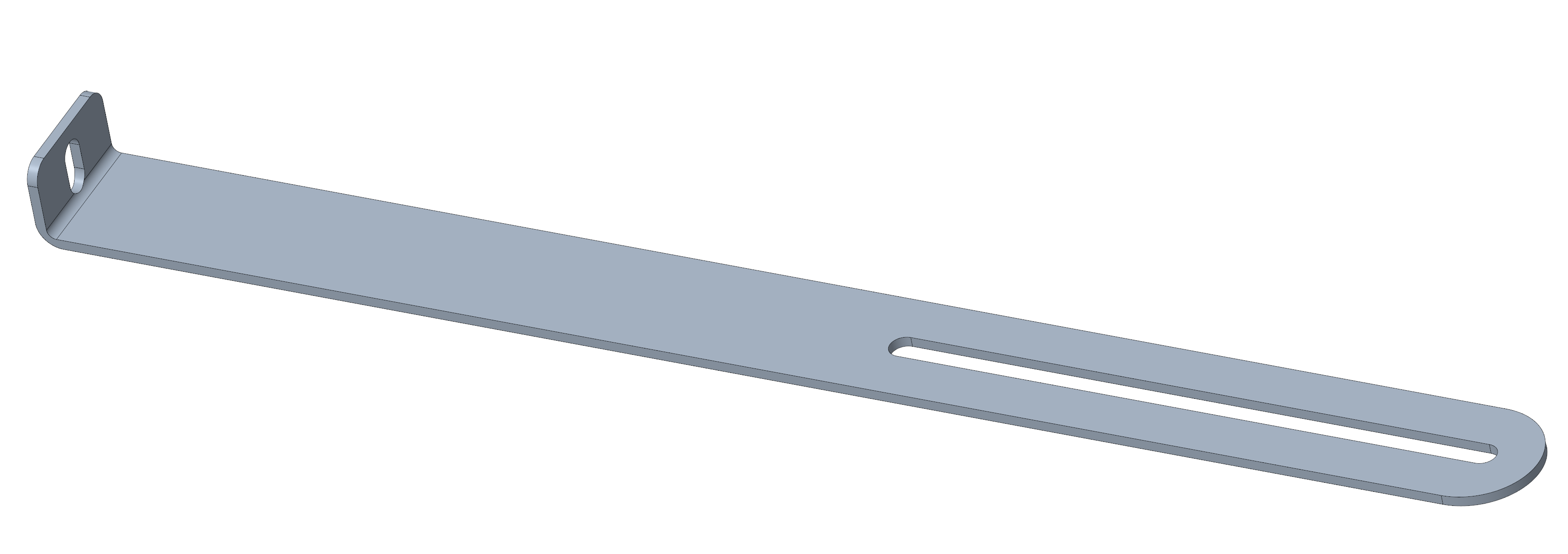
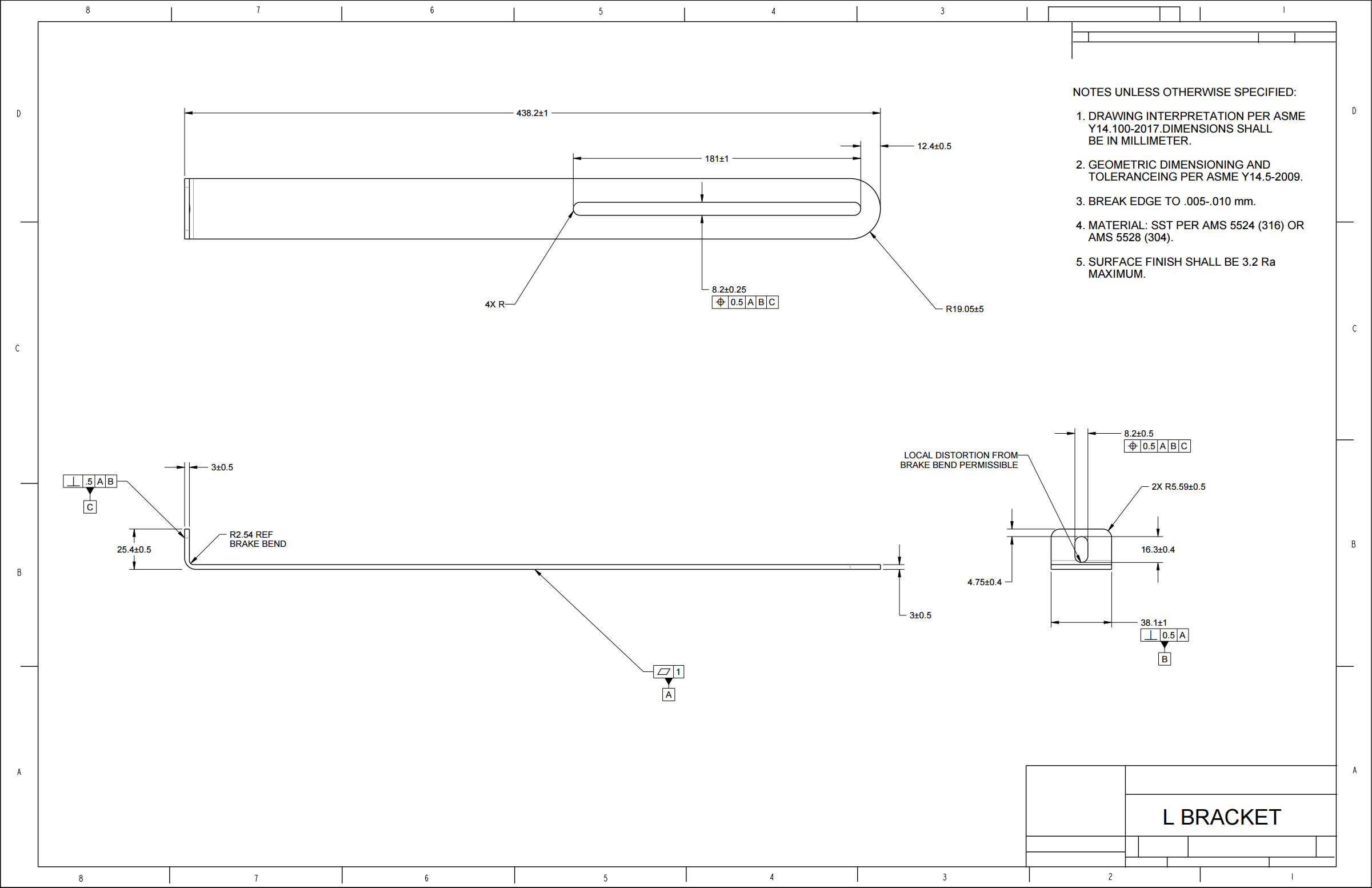
Always include a 2D drawing (PDF) alongside the 3D model for anything with tolerances, threads, or finish callouts. The 3D file says what the part is; the drawing says what actually matters about it.
2. Call out tolerances only where they matter
Every tolerance you tighten adds cost. Don't blanket the whole part at ±0.001" (±0.025 mm). Specify tight tolerances only on the features that mate, seal, or locate — bores, shoulders, dowel holes — and leave everything else at a standard machining tolerance. If a dimension doesn't have a functional reason to be tight, letting it float saves you money.
3. Flag the critical features
Tell us which surfaces are cosmetic, which faces are datums, and which dimensions are make-or-break. A quick note — "Face A is the sealing surface, keep it flat" — lets us set up the part correctly the first time instead of guessing and hoping.
4. Specify material and finish explicitly
"Aluminum" isn't enough — 6061 and 7075 machine and cost differently. Name the alloy or grade, the heat treatment if any, and the surface finish (as-machined, bead-blast, anodize type/color, plating). If you're not sure, describe the environment the part lives in and we'll recommend the right spec in the DFM review.
5. Check for manufacturability before you send
A few geometry habits cause most of the DFM flags:
Mind wall thickness
Thin walls chatter under machining and warp in molding. Keep them within the process's practical range.
Radius internal corners
Tools are round. A perfectly sharp internal corner can't be machined — add a radius or expect an added op.
Watch deep pockets
Very deep, narrow features need long tools that flex. Reducing depth-to-width keeps cost and risk down.
The short version
Send a STEP plus a dimensioned PDF, tighten only the tolerances that earn it, flag your critical features, name the exact material and finish, and give the geometry a manufacturability once-over. Do that and your quote comes back faster, cheaper, and closer to right.
Not sure about something? Send it anyway. Every quote includes a founder-reviewed DFM check — we'll catch what you missed before anything gets cut.
Don't have a CAD file yet? We'll create it.
This whole guide assumes you already have a model in hand — but plenty of great products start as a sketch, a rough idea, or a part already sitting on your shelf. That's completely fine. Value Trade Pro isn't only a manufacturer — we're engineers.
Bring us whatever you've got. A napkin sketch or a description becomes full 3D CAD and production-ready drawings. Already have a physical part? Mail it to us — we've had customers ship us a sample to reverse-engineer and then modify so it fits their own product line. Want to hold it in your hands before committing to a full run? We'll prototype it first.
Concept to CAD, reverse engineering, prototyping, drawings with proper tolerances and GD&T, and DFM from the first line — real engineering, plus the finished parts to match, all from one partner who takes it from idea to production.
See how our engineering services work →